You may know that the standalone XDS110 debugger has just been released on March 2017. Before that, XDS110 is only provided as part of LaunchPad. So, many months ago, I had a plan to design a standalone XDS110 debugger. The major consideration is to have the smallest form factor. For this requirement, I designed a new housing for my debugger as shown below.
But after the schematic and layout were completed, the project was suspended due to heavy loading on other projects.
Recently, I realize that I have to complete the project due to one major consideration: I have only one XDS100v3 debugger for all my CC26xx projects. This is dangerous for serious product development. I must have a backup. So, I have to either purchase a new XDS100 debugger or complete my own debugger.
Now, I have completed the debugger as shown below.
As you can see, the debugger is pretty small. But unlike the standard TI JTAG header, two 1.27mm pitch 14-pin headers are mounted on top & bottom sides of the debugger. The top one has the same pin-order of TI-14 connector. The bottom one is special designed for my own usage.
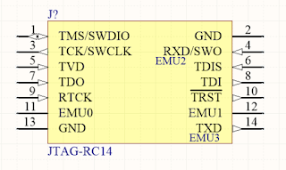
For most IoT applications, the target board is very small. But the TI-14 connector uses 2.54mm pitch header which is pretty large. So, I redesigned the pin definition for various applications. I call it RC-14. Here is the corresponding connector's schematic on target board.
What makes RC-14 so special? If your target board is really small then you can use cJTAG mode by only 4 pins (pin 1/2/3/4). You may notice that pin-4 is RXD/SWO which is actually connected to the 2nd UART channel (back channel) of the debugger. For JTAG mode (e.g. MSP432) where EMUx is not used then 8 pins can be used (pin 1~8). For old style DSP JTAG connection, you probably need to use all 14-pins which contains EMUx pinout.
You may also notice that cable is not used to connect the debugger and target board. Instead, the header is connected to target board directly. Since the debugger is so mall, there is no need to add a connection cable.
How to Make It?
First of all, I study the schematic from CC2640 and MSP432 LaunchPad to complete the circuit and layout. Then make the PCB by a manufacturer in China who provides the service to make small quantity engineering samples. For the major chip, TM4C129, I request a free sample from TI eStore. For other components, you can get them easily.
Finally, I tested the debugger by connect it to a CC2640-based target board. It can connect to the target and download program without any issue.
It is really great!
The next step is to print the housing for it. But... I don't have a 3D printer yet.


